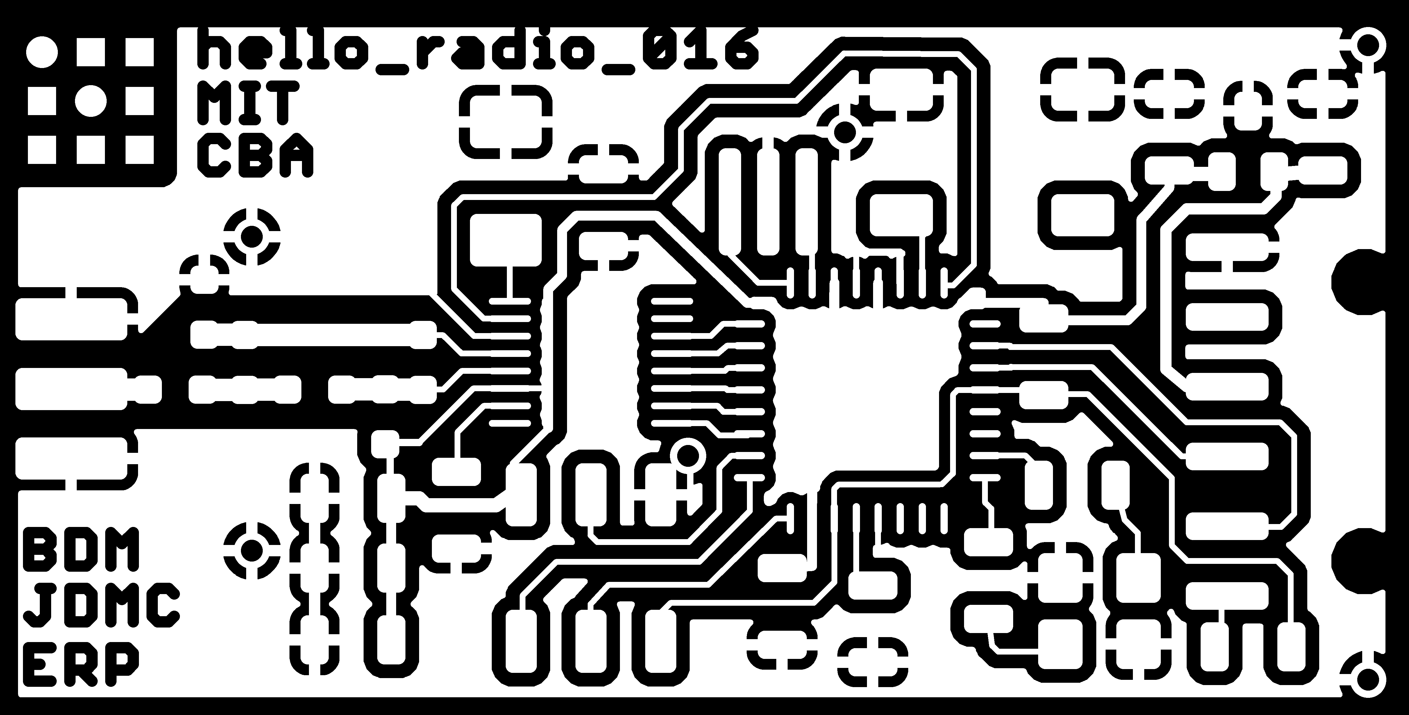
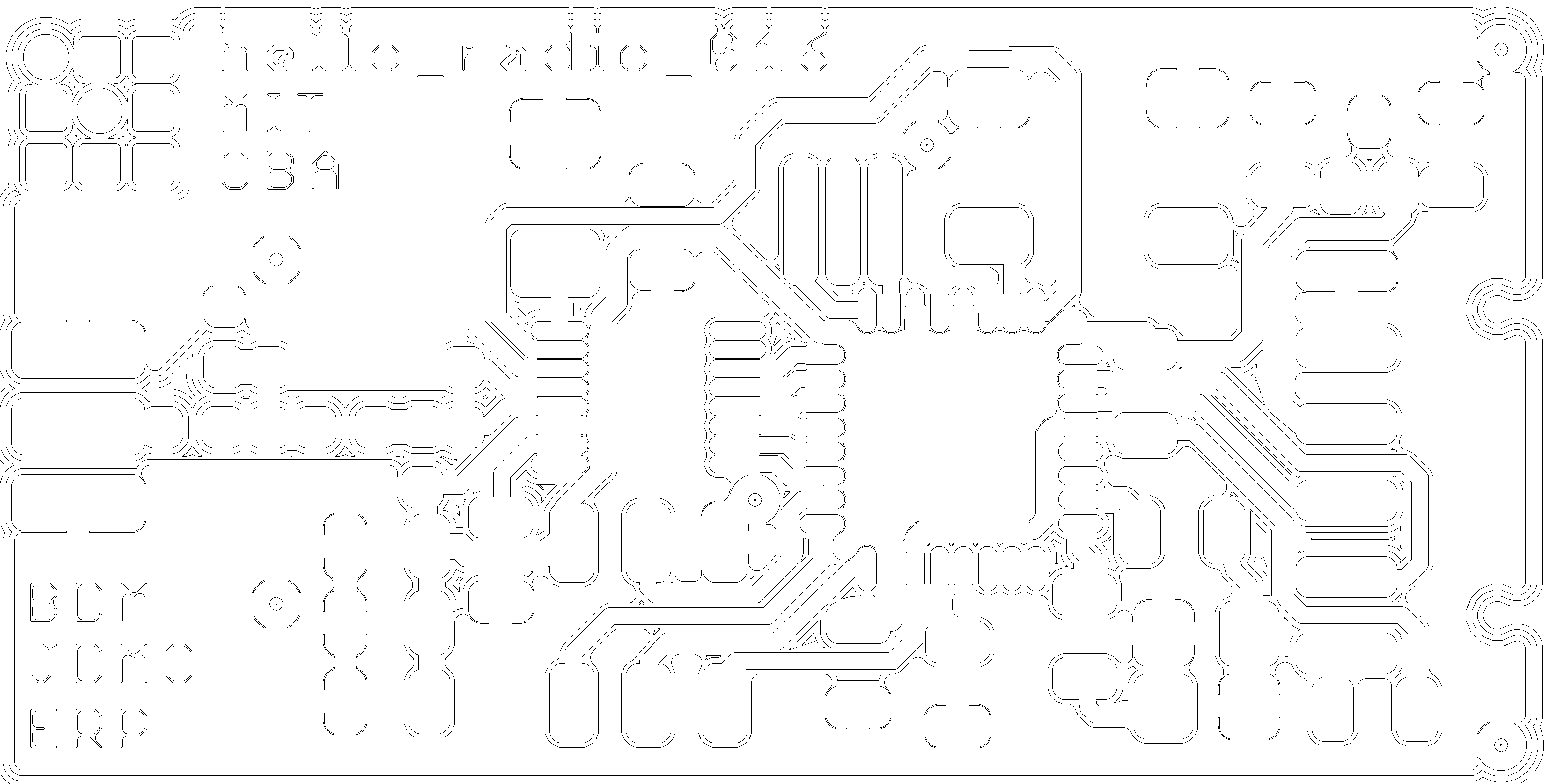
This week evolved into more of and advanced electronic production unit rather than networking. I constructed 3 hello_radio boards.
I started with the png files for the trace and ground plane layers an discovered an incompatability between the image files and Fab Modules. The version of Fab Modules in use at that point didn't always handle 1 bit indexed image file gracefully.
It took me a while to isolate the issue as the symptoms didn't immediately point me in the correct direction. I resolved the issue by using GIMP to convert the file into an 8 bit grey scale format.
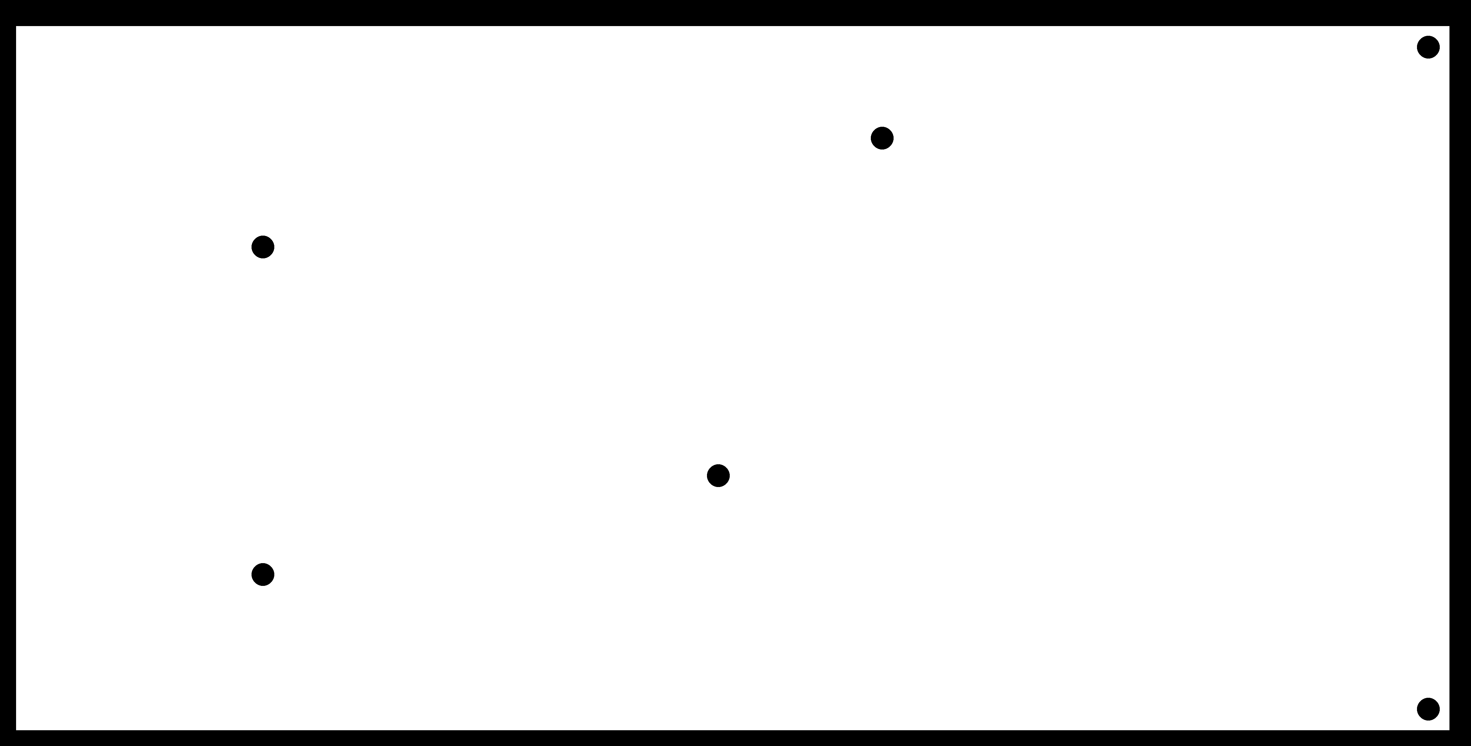
Neil has since updated Fab Modules once I reported the issue. Here are the tool path images.

I populated the boards and ran into two additional challenges. The assembly diagram and associated board layout were out of synch with the BOM and schematic. I reviewed the schematic and it seemed to be correct and match the BOM.
I assembled the boards with part placement based on the schematic and following the trace connections on the PCB.
The other challenge was a crystal needed for the radio IC that was not on our parts order list. At this point it was Monday so I placed an order with Digikey for the missing part with overnight delivery.
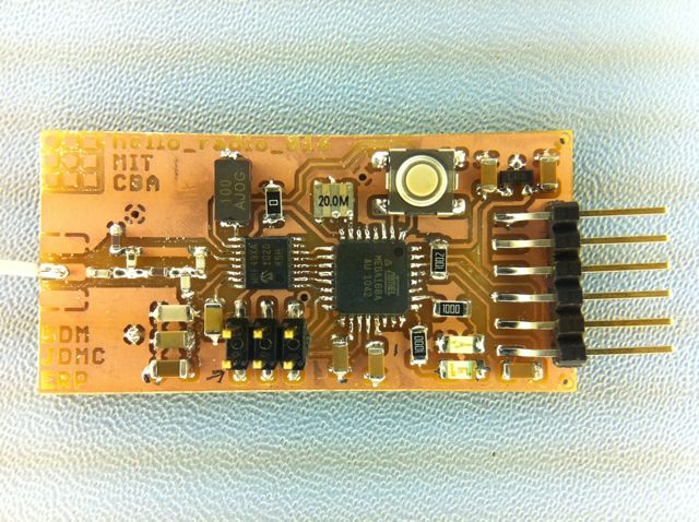
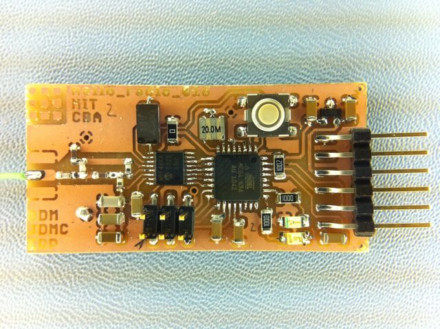
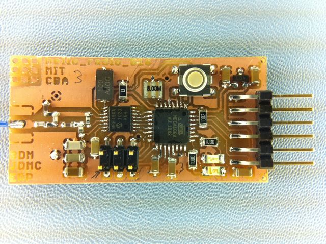
The boards assembled -
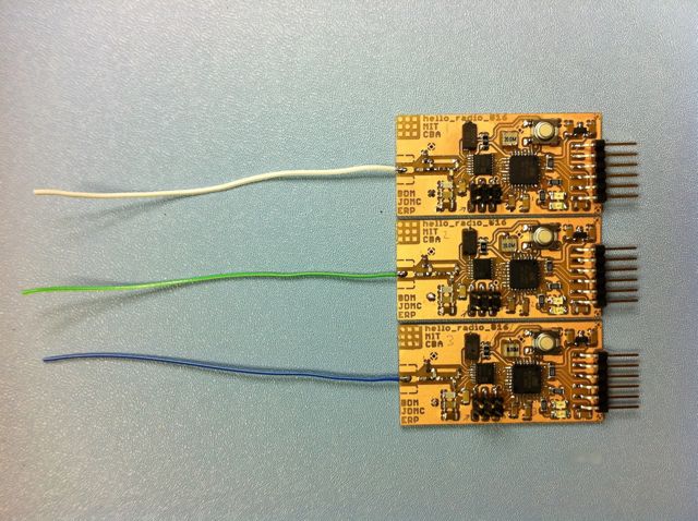
Boards 1 & 2 use 20MHz resonators for the processor. I used an 8MHz crystal on board 3 to evaluate performance differences with additional code on the radio board.
NOTE: Click on any of the images on these pages to enlarge.
I compiled the code with 2 different clock frequency constants to represent the different resonator frequencies (8 MHz and 20 MHz) that I used.
I used the FabISP board to program the code and fuses on the 3 hello_radio boards. Here is the text capture from the terminal during that programming.
I connected one of the boards to a computer using a FTDI cable and the other two to a 9V battery source (the current draw of the board with the 5.7V drop across the regulator doesn't overheat the regulator as it is mounted).
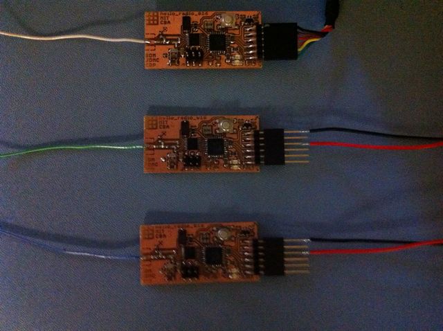
I used the onboard "Cmd_TXRX_button_loop" to transmit with the press of the pushbutton. Each board transmitted and received the other boards' transmissions.
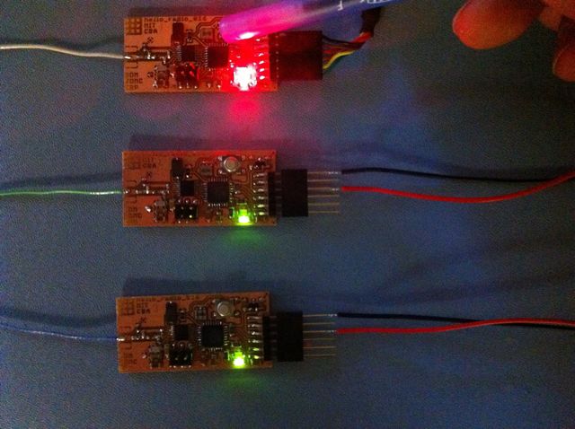
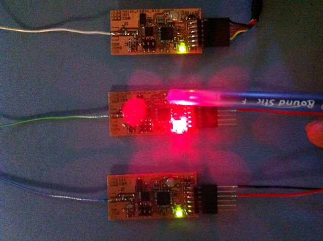
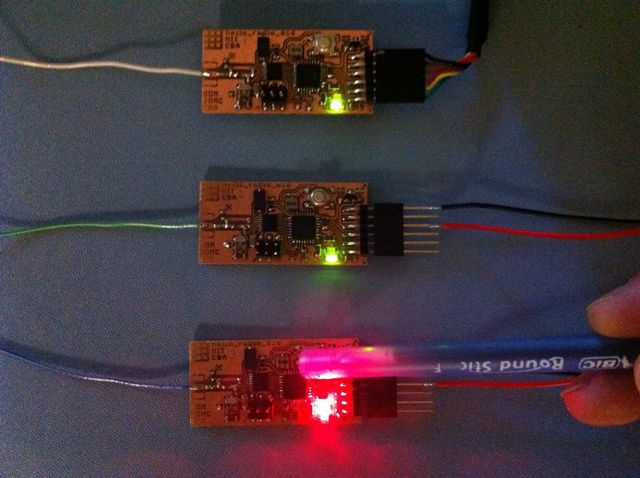
The serial communications during this testing session in captured here.
I moved one of the battery powered boards 70 feet from the other units and the communication still operated the lights with the switch. Serial communications.
With the challenges and the missing crystals arriving Tuesday afternoon I didn't have an opportunity to integrate the radios into a larger system.
Information on serial information and protocol would be useful.